Ao 9.00 Antenna Optimizer Program


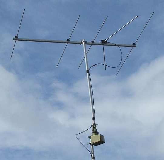
Antennacraft FM13 Antennacraft FM13 The Antennacraft FM13 is a log-Yagi array with 13 elements on a 137″ boom. Five of the elements are driven. I modeled the antenna with the AO 9.53 Antenna Optimizer program.
In simple language, a hedge is used to reduce any substantial losses or gains suffered by an individual or an organization. He wants to buy Company A shares to profit. Jcp Rewards Code And Serial Number.
This image shows the antenna geometry. This shows segmentation detail for the phasing lines and feedpoint. Blue dots mark analysis segments. The red dot is the feedpoint. Feedpoint Normally I jumper a wire across the feedpoint terminals and place a source at its center.
This model is unrealistic for the FM13 because the boom is between the terminals. A Radio Shack balun often used with the antenna has twin-lead split 3″ from the terminal lugs. I model this geometry instead. The resulting inductive reactance alters SWR, mismatch loss, and forward gain. Modeling Results Calculated performance is for 28 analysis segments per conductor halfwave with additional segments for the phasing lines. Forward gain includes mismatch and conductor losses. F/R is the ratio of forward power to that of the worst backlobe in the rear half-plane.